
Factory-direct from Lahore · Nationwide delivery in 2–4 days
+92 319 4262451
WhatsApp
A hospital is not one electrical building. It is three, stacked on the same site: ordinary circuits, circuits that have to survive a WAPDA outage, and equipment feeds written by the machine's manufacturer. Each group is sized a different way.
Ward circuits size on load. Essential boards size twice. Imaging feeds size on voltage drop.
Ordinary ward lighting and small power is ordinary building wiring, 1.5 to 6 mm² copper on the connected load. Anything fed through the standby changeover is sized on both sides, because the mains feed and the generator feed each carry the whole essential load alone. Equipment feeds are the ones that surprise people: an imaging room with a 45 A momentary demand, 40 m away, under the 2% drop limit its schedule sets, needs 25 mm² — not the 16 mm² the current alone would justify.
This is the load profile that makes a hospital different from an office of the same floor area. Read down the third column: the number that fixes the cable size changes from row to row.
| Circuit group | Typical size band | What actually fixes the size |
|---|---|---|
| Ward lighting and small power | 1.5 – 4 mm² | Connected load with normal diversity, as in any building |
| Theatre, ICU and other essential boards | 10 – 35 mm² | The whole essential load — on the mains side and the generator side of the changeover |
| Imaging rooms (X-ray, CT, MRI ancillaries) | 16 – 35 mm² | The momentary demand and the voltage-drop limit printed in the equipment schedule |
| Lifts, chillers, pumps, laundry plant | 6 – 25 mm² | Motor nameplate current plus starting behaviour |
Rows one and two are worked the ordinary way: total the load, apply diversity, then check the run — the method is on commercial load calculation and the kW-to-mm² ladder on 3-phase cable size. Row four is a motor feeder problem, worked on industrial cable sizing. Row three is the one nobody publishes, so it is worked below. Earthing and bonding conductors are sized off the phase conductor they protect, which is set out on earth cable.
Take a diagnostic room 40 m of cable route from its board on a 220 V single-phase feed. The equipment schedule — the manufacturer's, not ours — gives a 45 A momentary demand and holds the supply to a 2% drop at the machine's terminals. Read your own schedule; these two numbers are the whole job.
So the feed is 25mm 2 core cable, chosen by a voltage limit rather than by current. This is why an imaging room quote looks heavy next to a ward of the same floor area, and why substituting "one size down, it carries the amps anyway" on site is the wrong economy. Check any other run in the voltage drop calculator.
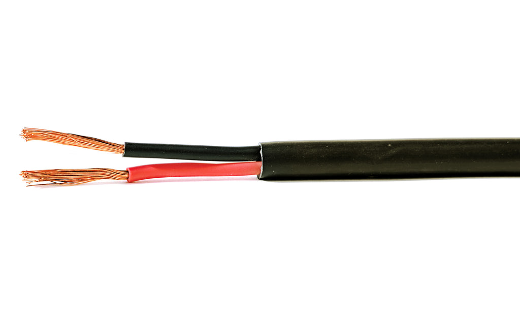
Class 5 copper for equipment tails and circuits that get re-dressed.
Class 2 copper for fixed ward wiring, submains and essential-board feeds.
One limit stated plainly, because a hospital is the wrong place to discover it late: our line is PVC insulated copper and aluminium at a 70 °C conductor rating. Fire-survival and low-smoke cable for life-safety circuits is a separate certified product class, and we do not make it or hold certificates for it. The full position is on fire resistant cable — send us the specification first and we will tell you plainly which lines of your schedule we can supply.
Size, cores and metres per line from the BOQ, or the load schedule itself. We will say which lines our range covers and which it does not.
Copper moves daily, so the quote carries its date. Factory-direct from the line that drew the cable, with no dealer margin.
Collect from Lahore, or we dispatch — Punjab in 1–2 days, rest of Pakistan in 2–4 days.
Send the schedule or the cable lines from the BOQ. You get the day's factory price against each one, and a straight answer on anything outside our range.