
Factory-direct from Lahore · Nationwide delivery in 2–4 days
+92 319 4262451
WhatsApp
Tonnage alone cannot determine the cable or breaker size for a 1.5-ton AC.
Start with the exact model’s nameplate and installation manual, then check the route, installation method, temperature, grouping and voltage drop. A 2.5 mm² or 4 mm² cable is a candidate only after those checks; neither is a universal recommendation.
Record the model and the manufacturer’s electrical requirements. Cooling tonnage is not electrical input power. Do not substitute a generic running-current or starting-current estimate for the equipment data.
| Item | What to confirm |
|---|---|
| AC model | Indoor and outdoor model numbers; inverter or fixed-speed |
| Electrical supply | Rated voltage, phase and frequency |
| Design current | Nameplate and manufacturer’s maximum operating/current requirements |
| Starting behaviour | Equipment data and required protective-device characteristics |
| Run length | Measured one-way cable route from the supply point |
| Installation | Conduit, tray, wall insulation, grouping and ambient temperature |
| Protection | Required device rating/type, breaking capacity and disconnection checks |
| Earthing | Protective conductor and termination requirements |
| Cable construction | Material, insulation, core count and permitted installation |
| Interconnecting cable | Follow the unit’s wiring diagram and manual |
| Isolation | Follow manufacturer and applicable installation requirements |
Use the cable-size calculator to explore a known load and route, then have an electrician verify its assumptions. Missing equipment information should be obtained from the manufacturer before installation.
A larger cross-section can reduce voltage drop, but choosing by size alone misses the insulation, installation and protection requirements.
Treat 2.5 mm² and 4 mm² as sizes to assess, not as answers attached to a tonnage label.
Sources for the selection method: Schneider Electric: cable sizing and installation conditions; Schneider Electric: protective-device selection. These references explain a process, not a Pilone product rating.
| Check | 2.5 mm² candidate | 4 mm² candidate | Decision evidence |
|---|---|---|---|
| Corrected current capacity | Check applicable cable table | Check applicable cable table | Actual method, insulation, loaded cores and correction factors |
| Voltage drop | Calculate for actual route | Calculate for actual route | Equipment tolerance and total circuit drop |
| Protection | Coordinate device and cable | Coordinate device and cable | Manufacturer requirements and fault/disconnection checks |
| Termination | Check conductor compatibility | Check conductor compatibility | Terminal capacity and cable construction |
A cable enclosed in a wall or grouped with other loaded circuits does not have the same thermal conditions as one installed in free air.
Select the correct reference installation method first. Apply the documented temperature and grouping corrections for that method; do not apply an arbitrary percentage to a convenient clipped-direct rating.
An electrician should coordinate the design current, protective device and corrected cable capacity, including fault protection. The inverter AC guide is related reading; the exact model’s manual remains essential.
Measure the one-way route, including rises and bends. Account for upstream voltage drop as well as the final AC circuit.
| Input | Record | Why it matters |
|---|---|---|
| Route length | One-way metres | Controls the length-dependent voltage loss |
| Current | Model-specific design current | Varies between equipment models and conditions |
| Cable data | Appropriate resistance/reactance or tabulated coefficient | Depends on construction, temperature and circuit |
| Supply path | Upstream circuit and actual supply conditions | Final-circuit drop is only part of the total |
| Acceptance limit | Applicable rules and manufacturer tolerance | Must be checked for the installation |
A per-amp, per-metre coefficient must match the cable, circuit configuration and calculation basis. Do not double a coefficient that already includes the return path. Use the voltage-drop calculator as a planning aid. Method reference: Schneider Electric: voltage-drop calculations.
Sirf 1.5 ton se wire size tay nahin hota. Model ki nameplate aur manual, cable ka one-way fasla, conduit, garmi aur grouping check karein.
2.5 mm² ya 4 mm² aur breaker ki rating electrician in maloomat ke mutabiq select kare. Model/nameplate aur run ki details bhejein; bina in details ke aik size har AC ke liye theek nahin kaha ja sakta.
Low supply voltage is a separate condition to investigate. Equipment behaviour depends on its controls and operating limits; assuming constant input watts at every voltage can give a misleading current estimate.
Have the supply and equipment checked against the manufacturer’s limits. Increasing conductor size may reduce circuit voltage loss, but it cannot guarantee an acceptable incoming supply.
The strand-code guide explains why 7/29 and 7/36 are not exact metric-size equivalents or current ratings. Specify nominal mm² and construction as well as a trade code.
| Field | Meaning | Quotation check |
|---|---|---|
| Strand code | Count and diameter under a stated convention | Confirm the units |
| Nominal mm² | Declared conductor size | Match the approved circuit schedule |
| Core count | Number of conductors within the cable | Match the wiring diagram and earthing arrangement |
| Construction | Material, conductor class and insulation | Confirm suitability for the route |
Once the design is confirmed, compare 4 mm² three-core standard and 4 mm² three-core flexible product entries where appropriate. Verify the selected construction and terminals; these links do not prescribe that size.
Measure each route on the planned installation. A multicore cable is ordered by route length; separate single-core conductors require their individual lengths to be totalled.
| Run | Measurement | Specification |
|---|---|---|
| Supply to unit / isolator | Measured route plus agreed allowances | Cable and protection approved by electrician |
| Indoor to outdoor unit | Measured interconnection route | Exact model’s installation manual |
| Separate protective conductor if required | Its actual route | Designed earthing arrangement |
Allow for termination and routing requirements agreed with the installer. A split system may need a separate indoor-to-outdoor cable with a different core count or specification.
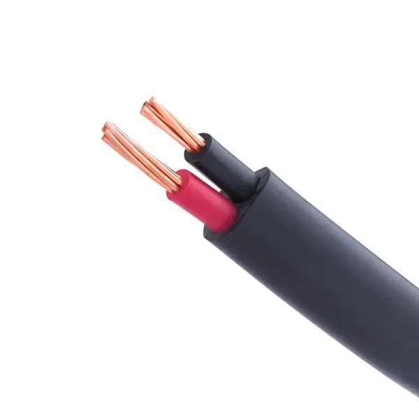
This existing product entry is one option to discuss after the circuit has been designed. Confirm the conductor, insulation, core count and approved size before ordering.
Request the selected construction and measured metres. Confirm availability and delivery with the quotation.
Other constructions include three-core standard and three-core flexible cable. The equipment diagram and installation determine which is suitable.
Send the model or nameplate, measured run, installation method and delivery city. Include the electrician’s selected cable specification when available.